Product Description
Model Selection
ZD Leader has a wide range of micro motor production lines in the industry, including DC Motor, AC Motor, Brushless Motor, Planetary Gear Motor, Drum Motor, Planetary Gearbox, RV Reducer and Harmonic Gearbox etc. Through technical innovation and customization, we help you create outstanding application systems and provide flexible solutions for various industrial automation situations.
• Model Selection
Our professional sales representive and technical team will choose the right model and transmission solutions for your usage depend on your specific parameters.
• Drawing Request
If you need more product parameters, catalogues, CAD or 3D drawings, please contact us.
• On Your Need
We can modify standard products or customize them to meet your specific needs.
Detailed Photos
Product Parameters
Features:
1) Dimensions of motors: 60mm, 70mm, 80mm, 90mm, 104mm can be choosed
2) Reduction ration:
A. 60mm, 70mm, 90mm Strengthen Type, 104mm: 3~200K
B. 80mm: 3~200k & 250~ 2000k(Mid Gearbox)
C. 90mm Normal Type: 3~ 750k
SPECIFICATION FOR AC MOTORS:
| MOTOR FRAME SIZE | 60 mm / 70mm / 80mm / 90mm / 104mm | ||
| MOTOR TYPE | INDUCTION MOTOR / REVERSIBLE MOTOR / TORQUE MOTOR / SPEED CONTROL MOTOR | ||
| SERIES | K series | ||
| OUTPUT POWER | 3 W / 6W / 10W / 15W / 25W / 40W / 60W / 90W / 120 W / 140W / 180W / 200W (can be customized) | ||
| OUTPUT SHAFT | 8mm / 10mm / 12mm / 15mm ; round shaft, D-cut shaft, key-way shaft (can be customized) | ||
| Voltage type | Single phase 100-120V 50/60Hz 4P | Single phase 200-240V 50/60Hz 4P | |
| Three phase 200-240V 50/60Hz | Three phase 380-415V 50/60Hz 4P | ||
| Three phase 440-480V 60Hz 4P | Three phase 200-240/380-415/440-480V 50/60/60Hz 4P | ||
| Accessories | Terminal box type / with Fan / thermal protector / electromagnetic brake | ||
| Above 60 W, all assembled with fan | |||
| GEARBOX FRAME SIZE | 60 mm / 70mm / 80mm / 90mm / 104mm | ||
| GEAR RATIO | MINIMUM 3:1—————MAXIMUM 750:1 | ||
| GEARBOX TYPE | PARALLEL SHAFT GEARBOX AND STRENGTH TYPE | ||
| Right angle hollow worm shaft | Right angle spiral bevel hollow shaft | L type hollow shaft | |
| Right angle CHINAMFG worm shaft | Right angle spiral bevel CHINAMFG shaft | L type CHINAMFG shaft | |
| K2 series air tightness improved type | |||
| Certification | CCC CE UL RoHS | ||
Other Related Products
Click here to find what you are looking for:
Company Profile
FAQ
Q: What’re your main products?
A: We currently produce Brushed Dc Motors, Brushed Dc Gear Motors, Planetary Dc Gear Motors, Brushless Dc Motors, Stepper motors, Ac Motors and High Precision Planetary Gear Box etc. You can check the specifications for above motors on our website and you can email us to recommend needed motors per your specification too.
Q: How to select a suitable motor?
A:If you have motor pictures or drawings to show us, or you have detailed specs like voltage, speed, torque, motor size, working mode of the motor, needed lifetime and noise level etc, please do not hesitate to let us know, then we can recommend suitable motor per your request accordingly.
Q: Do you have a customized service for your standard motors?
A: Yes, we can customize per your request for the voltage, speed, torque and shaft size/shape. If you need additional wires/cables soldered on the terminal or need to add connectors, or capacitors or EMC we can make it too.
Q: Do you have an individual design service for motors?
A: Yes, we would like to design motors individually for our customers, but it may need some mold developing cost and design charge.
Q: What’s your lead time?
A: Generally speaking, our regular standard product will need 15-30days, a bit longer for customized products. But we are very flexible on the lead time, it will depend on the specific orders.
/* January 22, 2571 19:08:37 */!function(){function s(e,r){var a,o={};try{e&&e.split(“,”).forEach(function(e,t){e&&(a=e.match(/(.*?):(.*)$/))&&1
| Application: | Motor, Machinery, Agricultural Machinery |
|---|---|
| Function: | Change Drive Torque, Change Drive Direction, Speed Changing, Speed Reduction |
| Layout: | Cycloidal |
| Hardness: | Hardened Tooth Surface |
| Installation: | Horizontal Type |
| Step: | Single-Step |
| Customization: |
Available
| Customized Request |
|---|
What are the potential challenges in designing and manufacturing spur gears?
Designing and manufacturing spur gears involve several challenges that need to be addressed to ensure optimal performance and reliability. Here’s a detailed explanation of the potential challenges in designing and manufacturing spur gears:
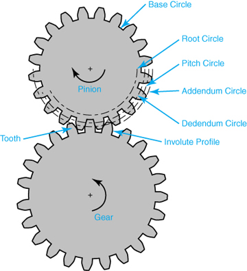
- Gear Tooth Design: Designing the gear tooth profile is a critical aspect of gear design. Achieving the desired tooth shape, pressure angle, and tooth thickness distribution while considering factors such as load capacity, durability, and noise generation can be challenging. Iterative design processes, computer-aided design (CAD) software, and gear design expertise are often employed to overcome these challenges.
- Material Selection: Choosing the appropriate material for gear manufacturing is crucial. Gears need to withstand high loads, transmit power efficiently, and exhibit excellent wear resistance. Selecting materials with suitable hardness, strength, and fatigue resistance can be challenging, especially when considering factors such as cost, availability, and compatibility with other components in the gear system.
- Manufacturing Processes: The manufacturing processes for producing spur gears, such as hobbing, shaping, or broaching, can present challenges. Achieving precise gear tooth profiles, accurate dimensions, and proper surface finish requires advanced machining techniques, specialized equipment, and skilled operators. Maintaining tight tolerances and ensuring consistent quality during mass production can also be demanding.
- Tooth Surface Finish: The surface finish of gear teeth plays a crucial role in gear performance. Achieving a smooth and precise tooth surface finish is challenging due to factors such as tool wear, heat generation during manufacturing, and the complexity of the gear tooth profile. Surface finishing processes, such as grinding or honing, may be required to achieve the desired surface quality.
- Noise and Vibration: Gears can generate noise and vibration during operation, which can affect the overall performance and user experience. Designing gears to minimize noise and vibration requires careful consideration of factors such as tooth profile optimization, load distribution, gear meshing characteristics, and proper lubrication. Conducting noise and vibration analysis and implementing appropriate design modifications may be necessary to address these challenges.
- Backlash Control: Controlling backlash, the slight gap between mating gear teeth, can be challenging. Backlash affects gear accuracy, smoothness of operation, and the ability to transmit torque efficiently. Balancing the need for adequate backlash to accommodate thermal expansion and minimize gear engagement issues while ensuring precise control of backlash can be a complex task in gear design and manufacturing.
- Heat Treatment: Heat treatment processes, such as carburizing or quenching, are often employed to enhance the hardness and strength of gear teeth. Proper heat treatment is crucial to achieve the desired material properties and gear performance. However, challenges such as distortion, residual stresses, and material property variations can arise during heat treatment, requiring careful process control, post-heat treatment machining, or additional treatments to mitigate these challenges.
- Quality Control: Ensuring consistent quality and reliability of spur gears is a challenge in manufacturing. Implementing effective quality control measures, such as dimensional inspections, hardness testing, and gear tooth profile analysis, is essential. Statistical process control (SPC) techniques and quality assurance systems help monitor manufacturing processes, identify potential issues, and maintain consistent gear quality.
- Cost and Time Constraints: Designing and manufacturing spur gears that meet performance requirements within cost and time constraints can be challenging. Balancing factors such as material costs, tooling expenses, production lead times, and market competitiveness requires careful consideration and optimization. Efficient production planning, cost analysis, and value engineering techniques are often employed to address these challenges.
By recognizing these challenges and employing appropriate design methodologies, manufacturing techniques, and quality control measures, it is possible to overcome the potential challenges associated with designing and manufacturing spur gears.
It’s important to note that the specific challenges may vary depending on the gear application, size, complexity, and operating conditions. Collaboration with gear design experts, manufacturing engineers, and industry specialists can provide valuable insights and guidance in addressing the challenges specific to your spur gear design and manufacturing processes.
How do you install a spur gear system?
Installing a spur gear system involves several steps to ensure proper alignment, engagement, and operation. Here’s a detailed explanation of how to install a spur gear system:
- Preparation: Before installation, gather all the necessary components, including the spur gears, shafts, bearings, and any additional mounting hardware. Ensure that the gear system components are clean and free from debris or damage.
- Shaft Alignment: Proper shaft alignment is crucial for the smooth operation of a spur gear system. Ensure that the shafts on which the gears will be mounted are aligned accurately and parallel to each other. This can be achieved using alignment tools such as dial indicators or laser alignment systems. Adjust the shaft positions as needed to achieve the desired alignment.
- Positioning the Gears: Place the spur gears on the respective shafts in the desired configuration. Ensure that the gears are positioned securely and centered on the shafts. For shafts with keyways, align the gears with the key and ensure a proper fit. Use any necessary mounting hardware, such as set screws or retaining rings, to secure the gears in place.
- Checking Gear Engagement: Verify that the teeth of the gears mesh properly with each other. The gear teeth should align accurately and smoothly without any excessive gaps or interference. Rotate the gears by hand to ensure smooth and consistent meshing throughout their rotation. If any misalignment or interference is observed, adjust the gear positions or shaft alignment accordingly.
- Bearing Installation: If the spur gear system requires bearings to support the shafts, install the bearings onto the shafts. Ensure that the bearings are the correct size and type for the application. Press or slide the bearings onto the shafts until they are seated securely against any shoulder or bearing housing. Use appropriate methods and tools to prevent damage to the bearings during installation.
- Lubrication: Apply a suitable lubricant to the gear teeth and bearings to ensure smooth operation and reduce friction. Refer to the gear manufacturer’s recommendations for the appropriate lubrication type and amount. Proper lubrication helps minimize wear, noise, and heat generation in the gear system.
- Final Inspection: Once the gears, shafts, and bearings are installed, perform a final inspection of the entire spur gear system. Check for any unusual noises, misalignment, or binding during manual rotation. Verify that the gears are securely mounted, shafts are properly aligned, and all fasteners are tightened to the specified torque values.
It’s important to follow the specific installation instructions provided by the gear manufacturer to ensure proper installation and operation. Additionally, consult any applicable industry standards and guidelines for gear system installation.
By carefully following these installation steps, you can ensure a well-aligned and properly functioning spur gear system in your machinery or equipment.
How do spur gears contribute to power transmission?
Spur gears play a crucial role in power transmission due to their specific design and tooth engagement. Here’s a detailed explanation of how spur gears contribute to power transmission:
- Direct Tooth Engagement: Spur gears have straight teeth that mesh directly with each other. This direct tooth engagement ensures efficient transfer of power from one gear to another. As the driving gear rotates, its teeth come into contact with the teeth of the driven gear, enabling the transfer of rotational motion and torque.
- Uniform Load Distribution: The teeth of spur gears distribute the transmitted load evenly across the gear surfaces. The straight, parallel teeth provide a larger contact area compared to other gear types, resulting in improved load-carrying capacity and reduced stress concentration. This uniform load distribution helps prevent premature wear and failure of the gears, ensuring reliable power transmission.
- Efficiency: Spur gears are known for their high efficiency in power transmission. The direct tooth engagement and parallel shaft arrangement minimize energy losses during rotation. The teeth mesh smoothly, resulting in minimal friction and reduced power dissipation. This efficiency is beneficial in applications where maximizing power transfer and minimizing energy waste are crucial.
- Speed and Torque Conversion: Spur gears allow for speed and torque conversion between the driving and driven shafts. By using gears with different numbers of teeth, the rotational speed and torque can be adjusted to match the requirements of the application. For example, a small gear driving a larger gear will result in a higher torque output at a lower speed, while a larger gear driving a smaller gear will result in a higher speed output at a lower torque.
- Directional Control: The arrangement of spur gears can be used to control the rotational direction of the driven shaft relative to the driving shaft. By meshing gears with opposite orientations (e.g., one gear with clockwise teeth and another gear with counterclockwise teeth), the direction of rotation can be reversed. This directional control is essential in applications where the desired motion needs to be reversed or changed.
- Multiple Gear Configurations: Spur gears can be combined in various configurations to form gear trains, allowing for complex power transmission systems. Gear trains consist of multiple gears meshing together, with each gear contributing to the overall power transmission. Gear trains can alter speed, torque, and direction, providing flexibility in adapting power transmission to specific requirements.
- Compatibility with Other Components: Spur gears are compatible with a wide range of other mechanical components, such as shafts, bearings, and housings. This compatibility allows for easy integration into different systems and machinery. Spur gears can be mounted on shafts using keyways, set screws, or other mounting methods, ensuring secure and reliable power transmission.
Overall, spur gears are essential in power transmission systems due to their direct tooth engagement, uniform load distribution, high efficiency, speed and torque conversion capabilities, directional control, compatibility with other components, and the ability to form complex gear trains. These characteristics make spur gears a versatile and widely used choice for transmitting power in various applications across industries.


editor by Dream 2024-05-06