Product Description
LYMC Custom ball mill pinion gear high quality forging big helical gear large spur gear
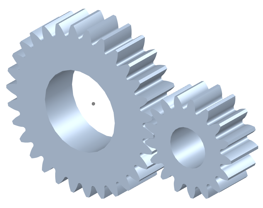
Gear transmission relies on the thrust between gear teeth to transmit motion and power, also known as meshing transmission. With this gradual meshing, helical gears operate much more smoothly and quietly than spur gears. Therefore, almost all automobile transmissions use helical gears.Since the teeth on the helical gear present a certain angle, the gears will be under a certain amount of stress when they mesh. Equipment using helical gears is equipped with bearings to withstand this pressure.
The precision of gear grinding precision gear can reach 5~6 levels. The corresponding dimensional accuracy can be achieved through precision gear grinding machine and grinder. It has the characteristics of stable transmission, low noise, long service life, and is suitable for high-power and heavy load.
|
Product name |
Spur Gear & Helical Gear & Gear Shaft |
|
Materials Available |
Stainless Steel, Carbon Steel, Brass, Bronze, Iron, Aluminum Alloy etc |
|
Heat Treatment |
Quenching & Tempering, Carburizing & Quenching, High-frequency Hardening, Carbonitriding…… |
|
Surface Treatment |
Carburizing and Quenching,Tempering ,Tooth suface high quenching Hardening,Tempering |
|
BORE |
Finished bore, Pilot Bore, Special request |
|
Processing Method |
Molding, Shaving, Hobbing, Drilling, Tapping, Reaming, Manual Chamfering, Grinding etc |
|
Pressure Angle |
20 Degree |
|
Hardness |
55- 60HRC |
|
Size |
Customer Drawings & ISO standard |
|
Package |
Wooden Case/Container and pallet, or made-to-order |
|
Certificate |
ISO9001:2008 |
|
Machining Process |
Gear Hobbing, Gear Milling, Gear Shaping, Gear Broaching, Gear Shaving, Gear Grinding and Gear Lapping |
|
Applications |
Toy, Automotive, instrument, electrical equipment, household appliances, furniture, mechanical equipment,daily living equipment, |
|
Advantages |
1. Produce strictly in accordance with ANSI or DIN standard dimension |
Product Process
Application:
About Us:
HangZhou MC Bearing Technology Co.,Ltd (LYMC),who is manufacture located in bearing zone, focus on Slewing bearing, cross roller bearing and pinion,Dia from 50mm-8000mm, Our team with technical and full experience in the bearing industry.
*Professional in researching, developing, producing & marketing high precision bearings for 16 years;
*Many series bearings are on stock; Factory directly provide, most competitive price;
*Advanced CNC equipment, guarantee product accuracy & stability;
*One stop purchasing, product include cross roller bearing, rotary table bearing, robotic bearing, slewing bearing, angular contact ball bearing, large and extra large custom made bearing, diameter from 50~9000mm;
*Excellent pre-sale & after sale service. We can go to customers’ project site if needed.
*Professional technical & exporting team ensure excellent product design, quotation, delivering, documentation & custom clearance.
Our Service:
FAQ:
1.Q: Are you trading company or manufacturer ?
A: We are professional slewing bearing manufacturer with 20 years’ experience.
2.Q: How long is your delivery time?
A: Generally it is 4-5 days if the goods are in stock. or it is 45 days if the goods are not in
stock, Also it is according to quantity.
3.Q: Do you provide samples ? is it free or extra ?
A: Yes, we could offer the sample, it is extra.
4.Q: What is your terms of payment ?
A: Payment=1000USD, 30% T/T in advance, balance before shipment.
5.Q: Can you provide special customization according to the working conditions?
A: Sure, we can design and produce the slewing bearings for different working conditions.
6.Q: How about your guarantee?
A: We provide lifelong after-sales technical service.
/* January 22, 2571 19:08:37 */!function(){function s(e,r){var a,o={};try{e&&e.split(“,”).forEach(function(e,t){e&&(a=e.match(/(.*?):(.*)$/))&&1
| Application: | Motor, Machinery, Marine, Agricultural Machinery, Mining, Petroleum, Automatic,Excavator,Crane, |
|---|---|
| Hardness: | Hardened Tooth Surface |
| Gear Position: | External Gear |
| Toothed Portion Shape: | Spur Gear |
| Material: | Stainless Steel |
| Type: | Non-Circular Gear |
| Customization: |
Available
| Customized Request |
|---|
How do you ensure proper alignment when connecting spur gears?
Proper alignment is crucial when connecting spur gears to ensure smooth and efficient gear operation. Here’s a detailed explanation of how to ensure proper alignment when connecting spur gears:
- Visual Inspection: Start by visually inspecting the gears, gear shafts, and associated components for any visible misalignment or damage. Look for signs of wear, uneven tooth engagement, or any abnormalities that may affect alignment.
- Shaft Alignment: Align the gear shafts accurately before connecting the gears. Proper shaft alignment ensures that the gears are positioned correctly relative to each other. This can be achieved through various alignment techniques, such as using alignment tools, laser alignment systems, or measuring devices. The goal is to ensure parallel or coaxial alignment between the gear shafts.
- Backlash Adjustment: Adjust the backlash between the gear teeth to achieve proper alignment. Backlash refers to the slight gap between the mating teeth of gears. It is important to maintain an appropriate amount of backlash to allow for smooth gear engagement and minimize the risk of binding or jamming. Follow the manufacturer’s recommendations or industry standards for the recommended backlash range and adjust as necessary during gear installation.
- Check Gear Mesh: Verify the gear meshing pattern to ensure proper alignment. The gear teeth should mesh smoothly and evenly without any signs of excessive or uneven contact. If there are indications of improper meshing, such as concentrated contact on a specific area of the tooth, it may imply misalignment or other issues that need to be addressed.
- Shim Adjustment: If misalignment is detected, shimming can be employed to correct it. Shimming involves placing thin metal shims between the gear and the shaft to adjust the positioning and alignment. Shims are available in various thicknesses, allowing for precise alignment adjustments. Careful measurement and selection of the appropriate shim thickness can help achieve the desired alignment.
- Tightening Bolts: When connecting the gears to the shafts, ensure that the bolts or fasteners are tightened evenly and to the recommended torque specifications. Uneven tightening can introduce misalignment or uneven load distribution, leading to gear misalignment and potential issues.
- Post-Installation Verification: After connecting the gears, perform a final verification of the alignment. Rotate the gears manually or through the gear system’s intended operation and observe the gear meshing behavior. Look for any signs of abnormal noise, vibration, or irregular tooth engagement. If any issues are detected, further adjustments or inspections may be necessary.
- Regular Maintenance: Implement a proactive maintenance program that includes periodic inspections and alignment verification. Gears can experience wear or misalignment over time due to factors such as load variations, temperature changes, or prolonged operation. Regular maintenance allows for early detection and correction of alignment issues, ensuring optimal gear performance and longevity.
Proper alignment is essential for maximizing the efficiency, durability, and reliability of spur gear systems. By following these alignment practices and considering the manufacturer’s recommendations, industry standards, and expert advice, you can ensure proper alignment when connecting spur gears.
It’s important to note that the specific alignment techniques and procedures may vary depending on the gear system’s design, size, application, and other factors. Consulting with gear manufacturers, engineers, or alignment specialists can provide further guidance on the recommended alignment practices for your specific gear system.
What is the purpose of using spur gears in machinery?
In machinery, spur gears serve several important purposes due to their unique characteristics and capabilities. Here’s a detailed explanation of the purpose of using spur gears in machinery:
- Power Transmission: Spur gears are primarily used for power transmission in machinery. They transfer rotational motion and torque from one shaft to another, allowing machinery to perform various tasks. By meshing the teeth of two or more spur gears together, power can be transmitted efficiently and reliably throughout the machinery.
- Speed Reduction or Increase: Spur gears enable speed reduction or increase in machinery. By combining gears with different numbers of teeth, the rotational speed can be adjusted to match the desired output speed. For example, using a larger gear driving a smaller gear can increase the speed output while reducing the torque, while the opposite arrangement can decrease the speed while increasing the torque.
- Torque Amplification: Spur gears can amplify torque in machinery. By using gears with different numbers of teeth, the torque can be adjusted to match the required output. For example, using a smaller gear driving a larger gear can increase the torque output while reducing the speed, while the opposite arrangement can decrease the torque while increasing the speed.
- Directional Control: Spur gears provide directional control in machinery. By meshing gears with opposite orientations, the rotational direction of the driven shaft can be reversed or changed. This directional control is crucial for machinery that requires bi-directional motion or needs to change the direction of operation.
- Mechanical Advantage: Spur gears offer a mechanical advantage in machinery. By utilizing gear ratios, spur gears can multiply or divide the force exerted on the input shaft. This mechanical advantage allows machinery to generate higher forces or achieve precise movements with reduced effort.
- Precision Positioning: Spur gears facilitate precise positioning in machinery. The accurate tooth engagement of spur gears ensures precise control over rotational motion, making them suitable for applications that require precise positioning or synchronization of components. Machinery such as CNC machines, robotics, and automation systems often rely on spur gears for accurate movement and positioning.
- Compact Design: Spur gears have a compact design, making them suitable for machinery with space constraints. They can be arranged in-line, parallel, or at right angles, allowing for efficient power transmission in tight spaces. Their compactness enables machinery to be designed with smaller footprints and optimized layouts.
- Reliability and Durability: Spur gears are known for their reliability and durability in machinery. The direct tooth engagement and uniform load distribution result in efficient power transmission with reduced wear and stress concentration. When properly lubricated and maintained, spur gears can withstand heavy loads and operate reliably over extended periods.
- Cost-Effectiveness: Spur gears are often cost-effective in machinery applications. Their simple design and ease of manufacturing contribute to lower production costs. Additionally, their high efficiency helps reduce energy consumption, resulting in potential long-term cost savings. The availability of spur gears in various sizes and materials further enhances their cost-effectiveness.
By utilizing spur gears in machinery, engineers and designers can achieve efficient power transmission, speed and torque control, directional versatility, mechanical advantage, precise positioning, compact design, reliability, durability, and cost-effectiveness. These advantages make spur gears a popular choice in a wide range of machinery applications across industries.
How do you choose the right size spur gear for your application?
Choosing the right size spur gear for your application requires careful consideration of various factors. Here’s a detailed explanation of the steps involved in selecting the appropriate size spur gear:
- Determine the Required Torque: Start by determining the torque requirements of your application. Calculate or estimate the maximum torque that the gear will need to transmit. Consider factors such as the power input, speed, and load conditions to determine the required torque.
- Identify the Speed Requirements: Determine the desired rotational speed or RPM (revolutions per minute) for your application. This will help in selecting a gear with the appropriate pitch diameter and tooth configuration to achieve the desired speed.
- Consider the Load Conditions: Evaluate the expected load conditions, including the magnitude and direction of the load. Determine if the load is constant or variable, and if it involves shock loads or cyclic loading. This will impact the gear’s durability and load-carrying capacity.
- Calculate the Pitch Diameter: Based on the torque and speed requirements, calculate the pitch diameter of the spur gear. The pitch diameter is determined by the formula: Pitch Diameter = (2 x Torque) / (Pressure Angle x Allowable Tooth Shear Stress).
- Select the Module Size: Choose an appropriate module size based on the gear size and application requirements. The module size determines the tooth size and spacing. Smaller module sizes are used for fine tooth profiles and higher precision, while larger module sizes are suitable for heavier loads and higher torque applications.
- Determine the Number of Teeth: Based on the pitch diameter and module size, calculate the number of teeth required for the gear. Ensure that the gear has an adequate number of teeth for smooth operation, load distribution, and sufficient contact ratio.
- Consider Space Constraints: Evaluate the available space and mounting requirements in your application. Ensure that the selected gear size can fit within the available space and can be properly mounted on the shaft or gearbox.
- Choose the Material: Consider the operating conditions, such as temperature, humidity, and presence of corrosive substances, to select the appropriate material for the spur gear. Common materials include steel, cast iron, brass, and plastic. Choose a material that offers the necessary strength, wear resistance, and durability for your specific application.
- Consider Additional Design Features: Depending on your application requirements, you may need to consider additional design features such as profile shift, hub configuration, and surface treatments. Profile shift can optimize gear performance, while specific hub configurations and surface treatments may be necessary for proper mounting and enhanced durability.
It’s important to note that gear selection is a complex process, and it may require consultation with gear manufacturers or experts in the field. They can provide guidance based on their expertise and assist in selecting the most suitable spur gear for your specific application.
By thoroughly considering factors such as torque requirements, speed, load conditions, pitch diameter, module size, number of teeth, space constraints, material selection, and additional design features, you can choose the right size spur gear that meets the demands of your application in terms of performance, durability, and efficiency.


editor by Dream 2024-04-30